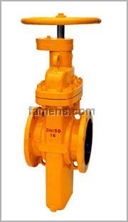
燃气闸阀*用于天然气、液体石油气煤气、油品等,它以独特的设计、新颖的结构和良好的密封性能彻底解决了阀门因燃气结焦而引起的关不严、开不动等问题,有效地提高了密封性能和使用寿命,真正达到零泄漏。
| 燃气闸阀 |
| 型号编制说明Model schedule illustration |
|
|
阀体材料代号Body material code
压力等级代号Pressure grade code
密封面材质代号Sealing formation code
结构特点代号Structure manner code
结构形式代号Design feature code
连接形式代号Connecting type code
驱动方式代号Driving manner code
阀门类型代号Valve type code
特殊要求代号Special requirement code
系列代号Series code
|
●系列代号:本公司系列代号为FY
Series code:The serles code name of our company is FY
●特殊要求代号:K-抗硫型L一调节型zB一自动补偿
SPeclal requl rement code:K-Antisulphur modeI L-Adjustment type ZB-Auto compensation
●阀门类型代号:2-闸阀
VaIve type code:ZmGate vaIve
●驱动方式代号:4-正齿轮传动 5-伞齿轮传动 9-电动 9B-防爆电动(手轮传动略)
Driving manner code:4-Spur gear transmission 5-Bevel gear transmission 9-Electric driving 9B—ExpIosion electric driving.(Hand wheel driving omitted)
●连接形式代号:4-法兰连接6-对焊连接
Connecting type code:4-Flange-joining 6-Buff welding joining
●结构形式代号:7-暗杆平行式单闸板
Design feature code:7-Dark Pole parallel single-disc
●结构特点代号:w-无导流孔(有导流孔省略)
Structure manner code:Wrenon-dive rsion hole type(Dlve rsion hoIe type omitted)
●密封面材质代号:F-增强聚四氟乙烯
Sealing formation code:F-Intensified polytetrafluoroethylene(PTFE)
●压力等级代号:公称压力为MPa的10倍、磅级为实际数
Pressure grade code:The 10 times of the nominal Pressure MPa Pound grade io Ptactlcal number
●阀门材料代号:阀体材料代号:C-WCB、P-CF8、ZGlCrl8Ni9Ti R-CF8M、ZGlCrl8Nil2Mo2Ti
BodY mate rial code:C-WCB、P-CF8、ZGlCrl8Ni9Ti R-CF8M、ZGlCrl8Nil2Mo2Ti
例1:Z543WF-16C
注释:公称压力为l 6MPa、伞齿轮传动、法兰连接、无导流孔、明杆平行式单闸板闸阀,阀体材质为WCB,密封面材质为增强聚四氟乙烯。
Example1:FYZ47F-10C
Note:PN=10Mpa.spur gear actuated.flange connected lnside stem Parallel type Single-disc gate valve with flow gulde hole.the body material is WCB and the sealing face material is reinforced PTFE.
例2:FY(K)Z67F-16C
注释:公称压力为l.6MPa、手动、对焊连接、有导流孔、抗硫暗杆平行式单闸板闸阀,阀体材质为WCB,密封面材质为增强聚四氟乙烯。
Example2:FY(K)Z67F-16C
Note:PN=1.6Mpa manually actuated butt—weld connected sulPhur resisting inside stem parallel type single-disc gate valve with flow guide hole the body material is WCB and the sealing face material is reinforced PTFE
|
产品结构特点Products design features
●阀体采用铸造结构。
The body uses a cast structure
●阀座采用O形密封圈密封和施加预紧力的浮动阀座结构,使阀门进出El双向密封;并且该结构的启闭力矩仅为普通阀门的l/2,能达到轻松开、关阀门。
The seat ring uses the floating seat ring structure with O-seal ting sealed and Pre-rightenmg fo rce apPIied to have mlet and outlet dual-way sealed;and the open-close moment wifh fhis structure is l/2 that of the common valves only,able to lightly open and close valves.
●阀座采用密封面上镶嵌PTFE,具有PTFE对金属和金属对金属的双重密封,PTFE密封面同时清除闸板脏物的作用。
The seat ring uses the sealing face inlaid with PTFE.so has dual seals of PTFE to metal and metal to metal,the PTFE sealing face also acts as removing the dirt on the wedge disc
●阀门的闸板,无论是全开或是全关始终与密封面吻合,密封面得到保护不受介质直接;中刷,从而延长使用寿命。
The wedge disc of the valve is always fitted with the sealing face whether in fullopen or fullclose status to have the sealing face Protected without being directly eroded by the medium so as to extend the duration.
●阀门在全开时,通道平滑为直线,流阻系数极小,无压力损失,可通毛球清扫管线。
When fully opened,the valve s channel is smooth and linear,with an extremely small flow resisting coefficient and no Pressure loss,and the Pipeline can be cleaned with hair-ball through it.
●阀门关闭时能自动卸掉内腔高压(详见工作原理图),保证使用安全。
Automatic removal of the hlgh Pressure in the internal cavity when the valve is about to close(see the working Principle dlagram for the details)so as to ensure safety.
●采用封闭齿轮转动启闭指示机构,能长期清晰地反映阀门的启闭情况。
Use a sealed gear-driving open-close indicating mechanism,which is able to clearly show the open-close condition of the valvein along term.
●直埋式阀门外表面采用环氧煤沥青防腐处理,能与管线同寿命。
The external surface of the directly built-in valve is corrosion resisting treated with epoxy coal bitumen and can be the same duration as the Pipeline.
|
产品性能规范Products performance specification
压力等级
Pressure |
常温试验压力(MPa)
Testing pressure at constant ternperature(Mpa) |
适用温度
Applicable
temperature |
适用介质
AppIicable medium
|
壳体试验
The shell testing |
左密封
Left sealing
|
右密封
Right sealing
|
低压气密封Low Pressure air tightness
|
普通型
0rdinary type |
抗硫型
Antisulphur type |
公称压力(MPa)
Nominal rating
pressure (PN) |
1.6 |
2.4 |
1.76 |
1.76 |
0.6 |
-29~121℃
或按用户要求
-29~121℃ or upon the user requirement
|
石油、天然气、水
等非腐蚀性介质
Petroleum natural gas warer etc non-
corroslve media
|
含H2S、C02的石油、天
然气、水等腐蚀性介质
Petroleum,natural gas,
water etc,containing H2S,
C02 corrosive media |
| 2.5 |
3.75 |
2.75 |
2.75 |
0.6 |
| 4.0 |
6.0 |
4.4 |
4.4 |
0.6 |
| 6.4 |
9.6 |
7.04 |
7.04 |
0.6 |
磅级(Lb)
Pound grade
(CIass) |
150 |
3.0 |
2.2 |
2.2 |
0.6 |
| 300 |
7.5 |
5.5 |
5.5 |
0.6 |
 |
1、阀门内部压力相当时(1),闸板处于闭合状态,阀座表面PTFE密封环形成初始密封,每次阀门开或关时,阀座圈能清洁闸板两侧。(如图l)
With equal Pressu re throughout the valve(and the gate in closed position),and initiaseal(1)is formed with the raised PTFE ring on the faces of the seats(The seat-inserts clean both sides of the gate each time the valve is opened or closed)
|
2、对阀门施加管道压力时(2),压力作用于闸板,迫使它贴近出I:1阀座上的PTFE环,压缩它直到闸板停在钢制阀座上,这样,就形成了双重密封,首先是PTFE对金属密封,然后是金属对金属密封,阀座也被牢固地推到凹槽,在这一点(3),0形圈阻止任何后部介质流。(如图2)
As line pressure(2)is applied to the valve it acts on the gate,forcing it against the PTFE ring on the downst ream seat,comp ressing it untiI the seat against the steel seat Thus,a double seal is formed first,a PTFE-t0-metal seal:then,metal-t0-metal The seat is also forced firmly into its recess The O-ring(3)p revents any downst ream flow at this point
|
 |
3、阀腔压力泄放后,形成进口密封,管道压力作用于进口阀座(4),使其移向闸板,这时形成PTFE对金属的密封,同时,0形圈(5)与阀座凹槽形成紧密的密封。(如图3)
Upstream seal is Provided when valve cavity Pressure is bled off This is caused by the force of line pressure acting against the upst ream seat(4)moving the seat against the gate and providing a tight PTFE-to metal seal at this point At the same time the O-ring(5)forms a tight seal with the seaf recess.
|
4、阀门自动泄放多余的压力,当阀腔压力大于管道压力时,由于热膨胀,进口阀座推向凹槽阀腔内多余的压力在阀座与闸板之间泄放到管道中。(如图4)
Valve automatically reIieves itself of excessive valve cavity Pressure When valve cavity Pressure exceeds line Pressure from such causes as thermal expansion the upstream seat is forced back into its recess and the excess Pressure in the valve cavity is bled between the seat and the gate into the line.
|
产品主要参数Main parameter of the products
| 基本型号Serial models |
Z47F、Z67F、Z447F、Z467F、Z547F、Z567F、Z9847F、Z9867F
|
| 压力等级范围Pressure grade range |
PN0.6~6.4MPa (Classl50~900) |
| 通径范围Drift diameter range |
DN25~1000mm (1“-40”) |
| 驱动方式Driving manner |
手轮驱动
Hand wheel driving |
齿轮动、气动、液动、电动 Gear driving,air-operating,hydrodynamic driving and electric driving |
| 适用范围Scope of application |
Classl50~300
(PNl.6~4.0) |
Class400
(PN6.4) |
Classl50~900 |
| 1"-40"(DN25-1000mm) |
1"-28"(DN25-700mm) |
1"-40"(DN25-1000mm) |
注:本公司可根据用户要求提供产品。
Note our company can provide Products at customres’request
|
|
产品采用标准Technical specification
| 设计依据Design reference |
GB |
API |
| 设计标准Design standard |
JB/T5298
GB/Tl9672 |
API 6D ASME Bl6.34 |
| 结构长度Structural length |
法兰
Flanged
|
GB/Tl2221
GB/Tl9672、JB/T5298 |
API 6D ASME Bl6.10 |
焊接
Welded connection |
GB/Tl5188.1
GB/Tl9672 |
连接法兰
Flanaed ends |
GB/T9113
JB/T79 |
ASME Bl6.5 MSS SP44 |
对焊端
Butt-welding ends
|
GB/Tl2224 |
ASME Bl6.25 |
试验和检验
Test&inspection |
JB/T9092 |
API 6D
APl598
|
注:阀门连接法兰尺寸可根据用户要求设计制造。
Note The sizes of valve connecting flange can be designed according to customers‘requirement |
|
|
主要零件材料Major parts material form
序号No.
|
零件名称
Accessory name |
材料Material |
| GB |
| 1 |
排污堵头Blow down stopple |
25 |
| 2 |
阀体Body |
WCB |
| 3 |
闸板 Gate disc |
16Mn+ENP |
| 4 |
阀座Seat |
16Mn |
| 5 |
O形圈 O-Ring
|
FPM |
| 6 |
密封圈 Sealing ring |
PTFE |
| 7 |
阀杆螺母 Valve Stem nut
|
ZQAL9-4 |
| 8 |
阀杆Stem |
1Cr13 |
| 9 |
垫片Gasket |
柔性石墨+1Crl8Ni9
Graphite+1Crl8Ni9 |
| 10 |
阀盖Bonnet
|
WCB |
| 11 |
双头螺母Stud |
35CrMo |
| 12 |
螺母 Nut |
45 |
| 13 |
O形圈 O-Ring |
FPM |
| 14 |
轴承 Bearing
|
组件Package |
| 15 |
对开环To the ring holding
|
45 |
| 16 |
内六角螺钉Six angle screws inside |
35 |
| 17 |
键Key
|
45 |
| 18 |
开关指示器Switch indicator
|
PTFE+1Crl8Ni9 |
| 19 |
手轮Hand wheel
|
Q235A |
| 20 |
螺母 Nut |
35 |
注:阀门主要零部件材质可根据实际工况条件或用户特殊要求设计选用。
Notes The majo r parts of the valves can be designed and selected according to actual work condition or customers’specific requirement |
|
|
|
产品采用标准Technical specification
| 设计依据Design reference |
GB |
API |
| 设计标准Design standard |
JB/T5298
GB/Tl9672 |
API 6D ASME Bl6.34 |
| 结构长度Structural length |
法兰
Flanged
|
GB/Tl2221
GB/Tl9672、JB/T5298 |
API 6D ASME Bl6.10 |
焊接
Welded connection |
GB/Tl5188.1
GB/Tl9672 |
连接法兰
Flanaed ends |
GB/T9113
JB/T79 |
ASME Bl6.5 MSS SP44 |
对焊端
Butt-welding ends
|
GB/Tl2224 |
ASME Bl6.25 |
试验和检验
Test&inspection |
JB/T9092 |
API 6D
APl598
|
注:阀门连接法兰尺寸可根据用户要求设计制造。
Note The sizes of valve connecting flange can be designed according to customers‘requirement |
|
|
主要零件材料Major parts material form
序号No.
|
零件名称
Accessory name |
材料Material |
| GB |
| 1 |
排污堵头Blow down stopple |
25 |
| 2 |
阀体Body |
WCB |
| 3 |
闸板 Gate disc |
16Mn+ENP |
| 4 |
密封圈 Sealing ring t |
16Mn |
| 5 |
阀座Seat
|
FPM |
| 6 |
密封圈 Sealing ring |
PTFE |
| 7 |
阀杆螺母 Valve Stem nut
|
ZQAL9-4 |
| 8 |
阀杆Stem |
1Cr13 |
| 9 |
O形圈 O-Ring |
FPM |
| 10 |
阀盖Bonnet
|
WCB |
| 11 |
O形圈 O-Ring |
FPM |
| 12 |
轴承 Bearing |
组件Package |
| 13 |
对开环To the ring holding |
45 |
| 14 |
内六角螺钉Six angle screws inside
|
45 |
| 15 |
双头螺柱 Stud
|
35CrMo |
| 16 |
螺母Nut |
45 |
| 17 |
键Key
|
45 |
| 18 |
开关指示器Switch indicator
|
组件Package |
注:阀门主要零部件材质可根据实际工况条件或用户特殊要求设计选用。
Notes The majo r parts of the valves can be designed and selected according to actual work condition or customers’specific requirement |
主要外形尺寸 Main size of outside
型号Model:(K)Z4(5,9B)4(6)7F PN0.4、0.6、1.0、2.5MPa PN2.0MPa(Class150)
DN
(mm)
|
NPS
(in) |
法兰
|
对焊 |
手动
|
齿动
|
齿动装置 |
电动
|
电动装置 |
| L |
L1 |
H1 |
H |
Do |
H1 |
H |
Do |
H1 |
H |
Do |
|
| 25 |
1 |
165 |
- |
85 |
228 |
180 |
- |
- |
- |
- |
- |
- |
- |
- |
| 32 |
1 1/4 |
165 |
- |
103 |
231 |
180 |
- |
- |
- |
- |
- |
- |
- |
- |
| 40 |
1 1/2 |
178 |
- |
115 |
240 |
250 |
- |
- |
- |
- |
- |
- |
- |
- |
| 50 |
2 |
178 |
216 |
130 |
255 |
250 |
- |
- |
- |
- |
- |
- |
- |
- |
| 65 |
2 1/2 |
190 |
241 |
160 |
355 |
300 |
- |
- |
- |
- |
- |
- |
- |
- |
| 80 |
3 |
203 |
283 |
180 |
360 |
300 |
- |
- |
- |
- |
- |
- |
- |
- |
| 100 |
4 |
229 |
305 |
214 |
400 |
300 |
- |
- |
- |
- |
- |
- |
- |
- |
| 125 |
5 |
254 |
381 |
257 |
460 |
350 |
- |
- |
- |
- |
- |
- |
- |
- |
| 150 |
6 |
267 |
403 |
300 |
500 |
350 |
- |
- |
- |
- |
- |
- |
- |
- |
| 200 |
8 |
292 |
419 |
388 |
570 |
350 |
- |
- |
- |
- |
- |
- |
- |
- |
| 250 |
10 |
330 |
457 |
475 |
680 |
400 |
475 |
700 |
350 |
0型 |
475 |
710 |
500 |
SMC-03 |
| 300 |
12 |
356 |
502 |
547 |
750 |
450 |
547 |
870 |
350 |
0型 |
547 |
880 |
305 |
SMC-00 |
| 350 |
14 |
381 |
572 |
625 |
875 |
450 |
625 |
995 |
450 |
1型 |
625 |
1015 |
305 |
SMC-00 |
| 400 |
16 |
406 |
610 |
721 |
1000 |
500 |
712 |
1120 |
450 |
1型 |
712 |
1130 |
305 |
SMC-00 |
| 450 |
18 |
432 |
660 |
785 |
1130 |
500 |
785 |
1280 |
450 |
1型 |
785 |
1360 |
305 |
SMC-0 |
| 500 |
20 |
457 |
711 |
880 |
1200 |
600 |
880 |
1350 |
450 |
1型 |
880 |
1430 |
305 |
SMC-0 |
| 600 |
24 |
508 |
813 |
1045 |
1420 |
800 |
1045 |
1570 |
500 |
2型 |
1045 |
1650 |
305 |
SMC-1 |
| 700 |
28 |
610 |
914 |
1190 |
1650 |
800 |
1190 |
1800 |
500 |
2型 |
1190 |
1910 |
305 |
SMC-1 |
| 800 |
32 |
660 |
914 |
1360 |
1880 |
1000 |
1360 |
2040 |
500 |
2型 |
1360 |
2140 |
305 |
SMC-1 |
| 900 |
36 |
771 |
1016 |
1510 |
2100 |
1000 |
1510 |
2280 |
600 |
3型 |
1510 |
2390 |
458 |
SMC-2 |
| 1000 |
40 |
811 |
- |
1715 |
2300 |
1200 |
1715 |
2480 |
600 |
3型 |
1715 |
2590 |
458 |
SMC-2 |
主要外形尺寸 Main size of outside
型号Model:(K)Z4(5,9B)4(6)7F PN0.4MPa PN5.0MPa(Class300)
DN
(mm)
|
NPS
(in) |
法兰
|
对焊 |
手动
|
齿动
|
齿动装置 |
电动
|
电动装置 |
| GB |
API |
L1 |
H1 |
H |
Do |
H1 |
H |
Do |
H1 |
H |
Do |
|
| 25 |
1 |
165 |
165 |
165 |
85 |
228 |
180 |
- |
- |
- |
- |
- |
- |
- |
- |
| 32 |
1 1/4 |
178 |
178 |
178 |
103 |
231 |
180 |
- |
- |
- |
- |
- |
- |
- |
- |
| 40 |
1 1/2 |
190 |
190 |
190 |
115 |
240 |
250 |
- |
- |
- |
- |
- |
- |
- |
- |
| 50 |
2 |
216 |
216 |
216 |
130 |
255 |
250 |
- |
- |
- |
- |
- |
- |
- |
- |
| 65 |
2 1/2 |
241 |
241 |
241 |
160 |
355 |
300 |
- |
- |
- |
- |
- |
- |
- |
- |
| 80 |
3 |
283 |
283 |
283 |
180 |
360 |
300 |
- |
- |
- |
- |
- |
- |
- |
- |
| 100 |
4 |
305 |
305 |
305 |
214 |
400 |
300 |
- |
- |
- |
- |
- |
- |
- |
- |
| 125 |
5 |
381 |
381 |
381 |
257 |
460 |
350 |
- |
- |
- |
- |
- |
- |
- |
- |
| 150 |
6 |
403 |
403 |
403 |
300 |
500 |
350 |
- |
- |
- |
- |
- |
- |
- |
- |
| 200 |
8 |
419 |
419 |
419 |
388 |
570 |
350 |
338 |
710 |
350 |
0型 |
338 |
720 |
305 |
SMC-00 |
| 250 |
10 |
457 |
457 |
457 |
475 |
680 |
400 |
475 |
820 |
350 |
0型 |
475 |
830 |
305 |
SMC-00 |
| 300 |
12 |
502 |
502 |
502 |
547 |
750 |
450 |
547 |
900 |
450 |
1型 |
547 |
910 |
305 |
SMC-0 |
| 350 |
14 |
572 |
762 |
762 |
625 |
875 |
450 |
625 |
1015 |
450 |
1型 |
625 |
1095 |
305 |
SMC-0 |
| 400 |
16 |
610 |
838 |
838 |
721 |
1000 |
550 |
712 |
1150 |
450 |
1型 |
712 |
1230 |
305 |
SMC-0 |
| 450 |
18 |
660 |
914 |
914 |
785 |
1130 |
700 |
785 |
1300 |
500 |
2型 |
785 |
1400 |
305 |
SMC-1 |
| 500 |
20 |
711 |
991 |
991 |
880 |
1200 |
800 |
880 |
1370 |
500 |
2型 |
880 |
1470 |
305 |
SMC-1 |
| 600 |
24 |
787 |
1143 |
1143 |
1045 |
1440 |
1000 |
1045 |
1620 |
600 |
3型 |
1045 |
1730 |
305 |
SMC-1 |
主要外形尺寸 Main size of outside
型号Model:(K)Z4(5,9B)4(6)7F PN6.4MPa (Class600)
DN
(mm)
|
NPS
(in) |
法兰
|
对焊 |
手动
|
齿动
|
齿动装置 |
电动
|
电动装置 |
| L |
L1 |
H1 |
H |
Do |
H1 |
H |
Do |
H1 |
H |
Do |
|
| 50 |
2 |
216 |
250 |
158 |
265 |
300 |
- |
- |
- |
- |
- |
- |
- |
- |
| 65 |
2 1/2 |
241 |
280 |
190 |
365 |
300 |
- |
- |
- |
- |
- |
- |
- |
- |
| 80 |
3 |
283 |
310 |
225 |
375 |
350 |
- |
- |
- |
- |
- |
- |
- |
- |
| 100 |
4 |
305 |
350 |
255 |
420 |
350 |
- |
- |
- |
- |
- |
- |
- |
- |
| 125 |
5 |
381 |
400 |
275 |
480 |
400 |
- |
- |
- |
- |
- |
- |
- |
- |
| 150 |
9 |
403 |
450 |
330 |
520 |
400 |
- |
- |
- |
- |
- |
- |
- |
- |
| 200 |
8 |
419 |
550 |
410 |
590 |
500 |
388 |
710 |
350 |
0型 |
388 |
720 |
305 |
SMC-0 |
| 250 |
10 |
457 |
650 |
490 |
700 |
500 |
475 |
820 |
350 |
0型 |
475 |
830 |
305 |
SMC-0 |
| 300 |
12 |
502 |
750 |
570 |
780 |
600 |
547 |
900 |
450 |
1型 |
547 |
910 |
305 |
SMC-0 |
| 350 |
14 |
762 |
850 |
625 |
910 |
600 |
625 |
710 |
350 |
1型 |
625 |
720 |
305 |
SMC-1 |
| 400 |
16 |
838 |
950 |
735 |
1020 |
700 |
712 |
820 |
350 |
1型 |
712 |
830 |
305 |
SMC-1 |
|


 1140282332 | 最新产品 | 最新供应 | 阀财通档案 | 公司介绍


